
Reference Attachment Methods in MicroStation

Following are attachment methods available in microstation:


1. Recommended: 

If you set the attachment method menu to recommended, the model or saved view is attached with default settings without opening the reference attachment settings dialog. The default settings are saved in workspace configuration file using a system variable (MS_REF_DEFAULTSETTINGS) and can be edited using edit button as shown in below image.


2. Interactive: 

If you set the attachment method menu to interactive, it will open up the reference attachment settings dialog to further define the orientation of the view (Coincident/Coincident World/Standard Views/Saved Views/Named Fences). This method allows placement of a model that is not geographically located with the active file. By using this method, you can choose point of placement manually. An example of use with the Interactive model would be when attaching a profile drawing to a plan and profile sheet.


3. Coincident: 

When you attach, a reference using the Coincident setting, microstation lines up the reference to the design plane coordinates only and does not take into account the location of the global origin. That means the design plane of reference file overlaps the design plane of active file and not considering the global origin. So when you work on your model by referencing another discipline's model and forget to set coordinate system, using coincident method while referencing brings things on correct location.


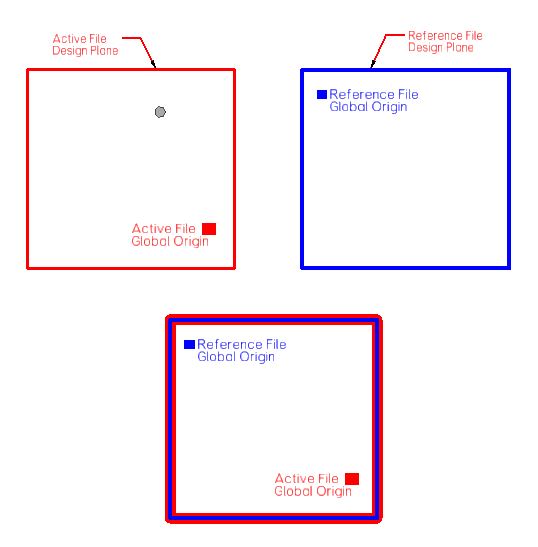
4. Coincident World: 

When you attach, a reference using the Coincident World setting, microstation lines up the reference to the global origin of the files. The elements in the attached reference, falls on the correct coordinate. Use this setting when the global origin is in a different location than that of the active file. The Coincident World setting can be loosely represented as follows:


5. Top/Bottom/Left/Right/Front/Back/Isometric/Right Isometric: 

These methods are used when we reference a 3D model and want these specific view to attach in the active model.


Comments

Popular posts from this blog

View Display, Global Display And Global Freeze In MicroStation

Level Display dialog in MicroStation is used to turn on and turn off levels in a model. This dialog contains the display control options (on/off switches): View Display, Global Display and Global Freeze as shown in below image. View Display If you are in "View Display" mode, changes in the level display affect the chosen (selected) view in the active model. This means that when you select/deselect a level in the level display dialog, it will turn on/off that level in the selected view only. It doesn't affect other views. Thus it has a local effect. Global Display  If you are in "Global Display" mode, changes in the level display affect all views in all models in the open file. This means that when you select/deselect a level in the level display dialog, it will turn on/off that level in all the open views. Thus it has a global effect. Global Freeze Changes in the level display affect all views in all models in the open file. When Global Freeze is on, elements on

Design Model, Drawing Model And Sheet Model In MicroStation

 There are three types of models available in microstation Design Model A design model is a collection of elements that are drawn for creation of desired model. The design model is drawn to actual size. A design model can be a 2D or a 3D model. You can create it by clicking the Create Model icon in the Models dialog and selecting the Type setting as Design or Design from Seed. In the design model, you can create the design of your project such as a building, bridge, road etc. Design model typically has a black background. Drawing Model A drawing model is an optional intermediate stage between the 3D design and sheet model. The drawing model is a 2D model in which you reference a design at full scale to add annotations, dimensions, callouts and other embellishments. It typically has a gray background. Sheet Model A sheet model contains design model references that are scaled and positioned to create a printable drawing. It can be considered as an electronic drawing sheet. Sheet mo